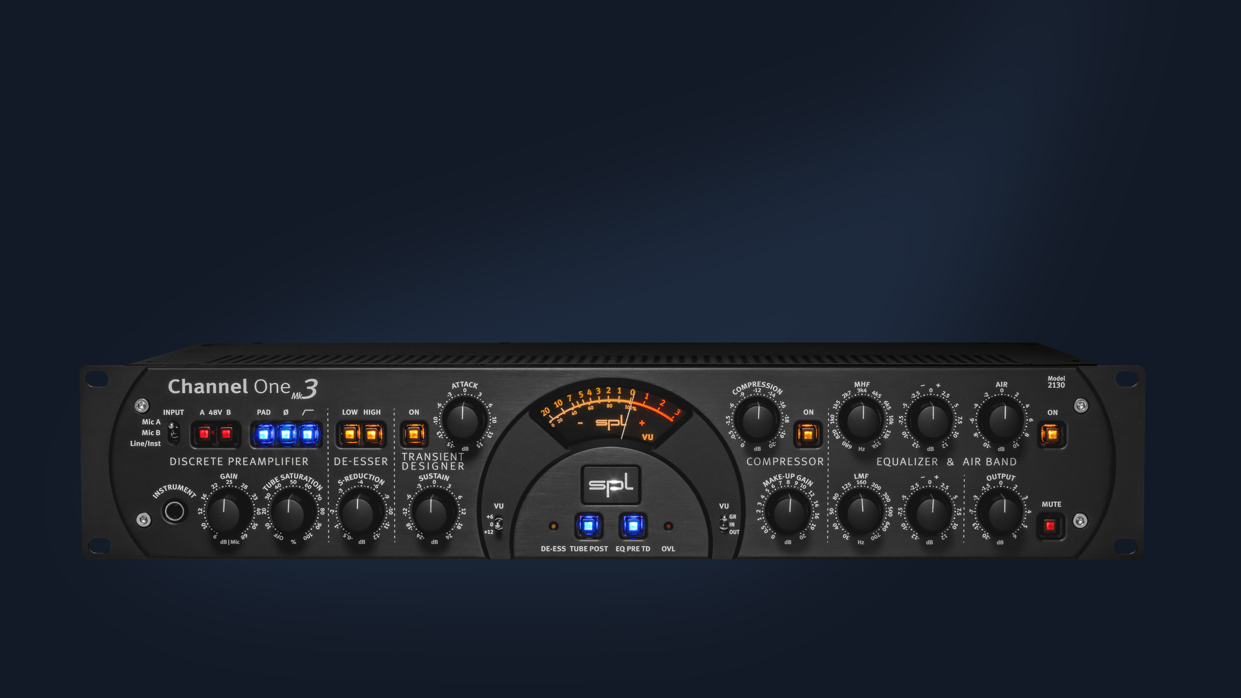
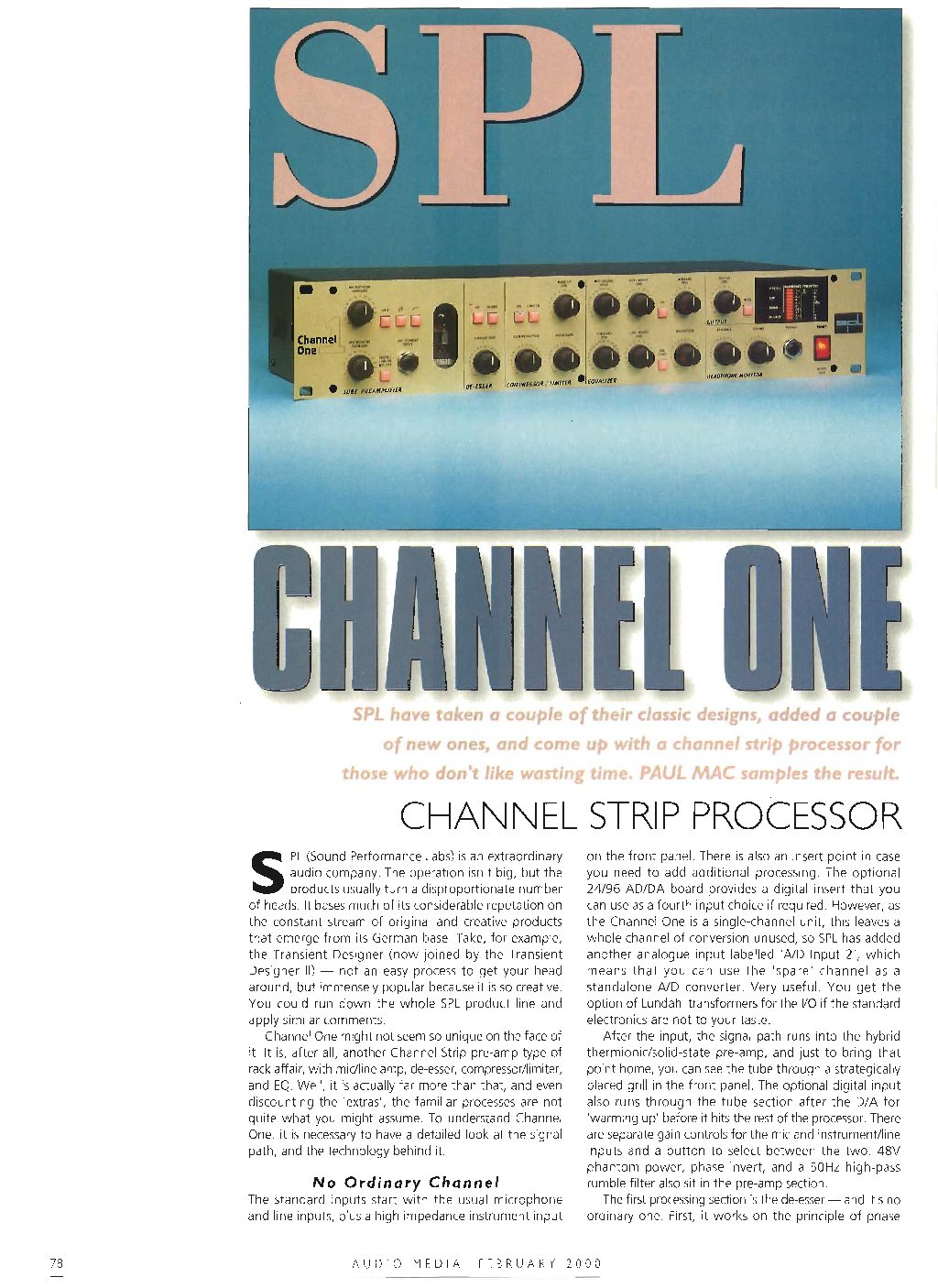
For over 20 years, Channel One has been a synonym for a high-quality and extremely musical recording and mixing channel strip.
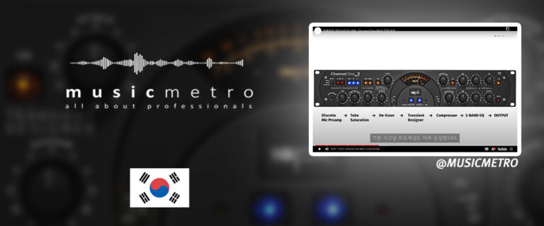
In the newest Mk3 version, this classic has been thoroughly revised and, in addition to a higher internal audio voltage (now +/-18 V) for even better, more detailed sound, a further improved preamplifier section, an integrated Transient Designer, a Tube Saturation stage and a Mic A/B comparison option for two microphones and other great features that raise the modern recording and mixing studio to a new level of quality. With de-esser, compressor and equalizer, all the important tools of a real channel strip are still on board. Whether it’s a microphone, line, or instrument signal, the Channel One Mk3 makes any source sound like a professionally recorded signal.
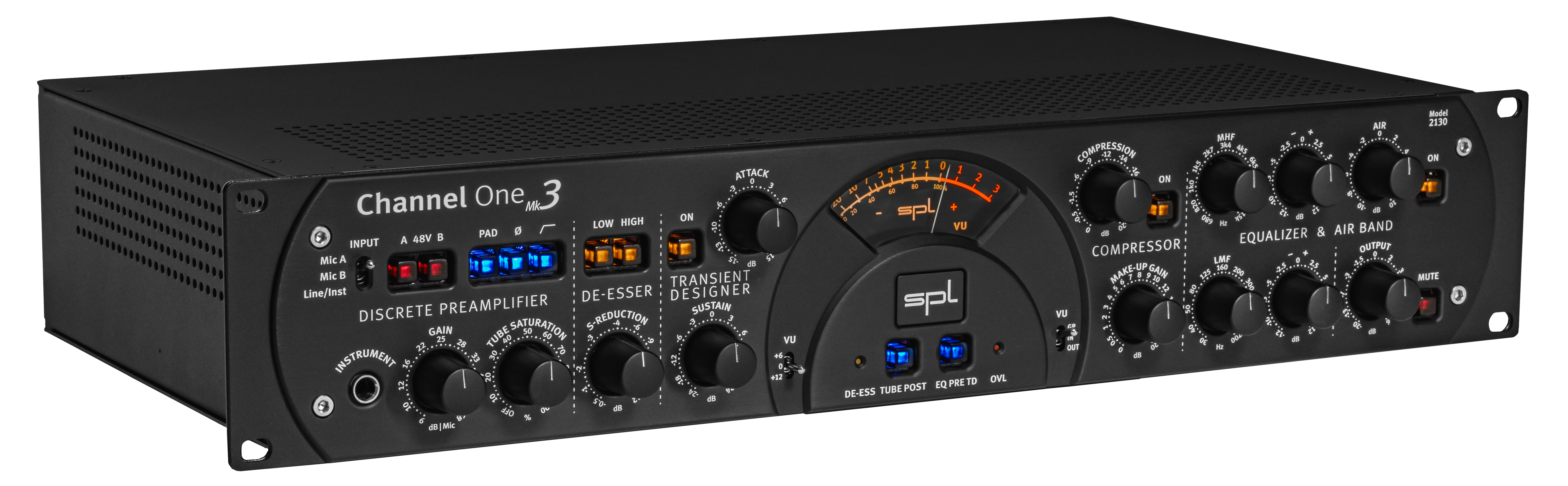
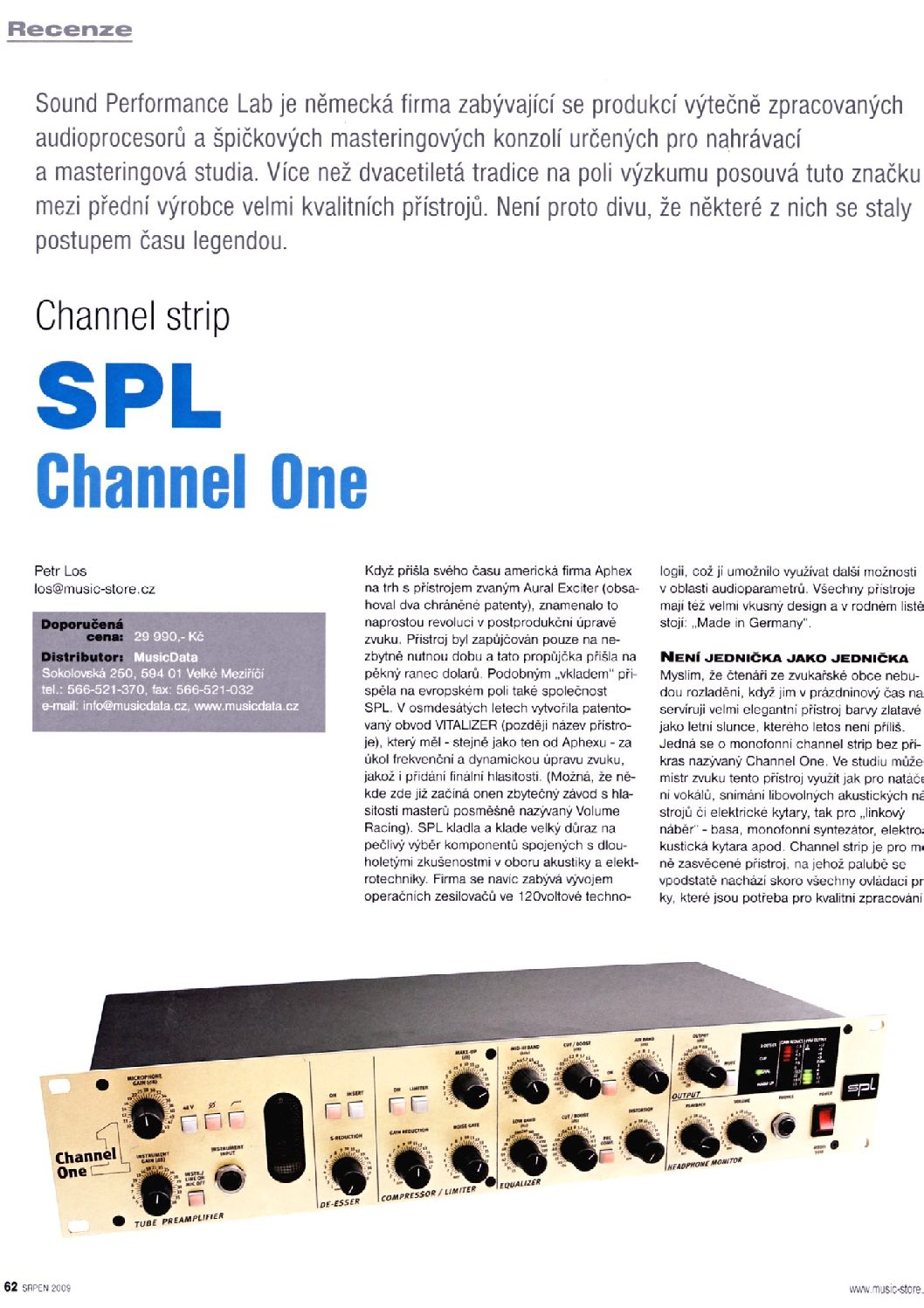
The new design of the SPL Studio Series perfectly highlights the sonic qualities of this 3rd generation Channel One.
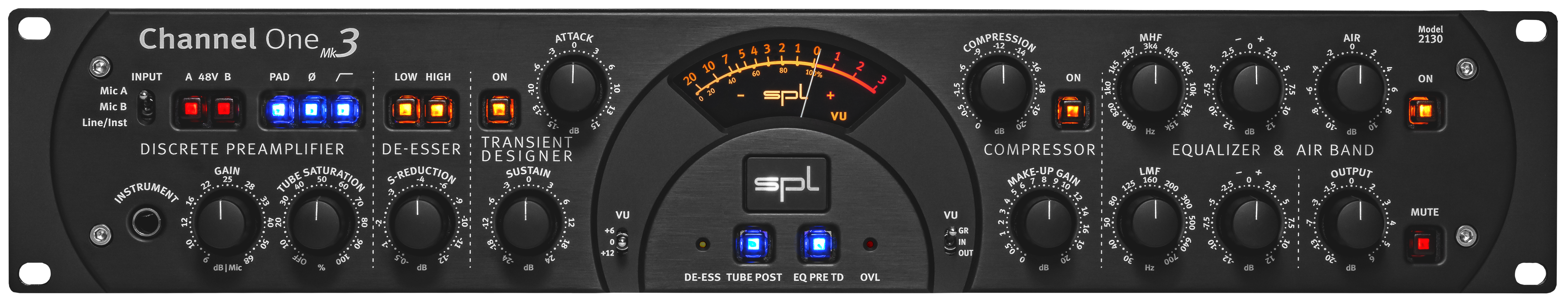
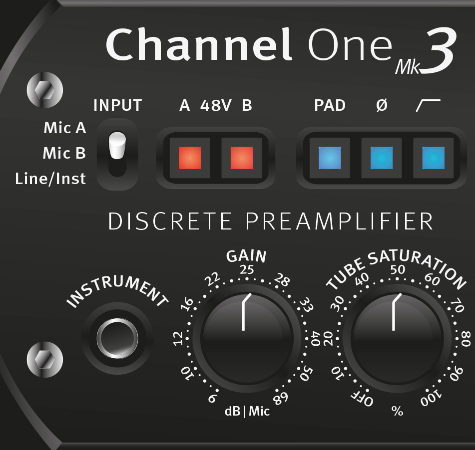
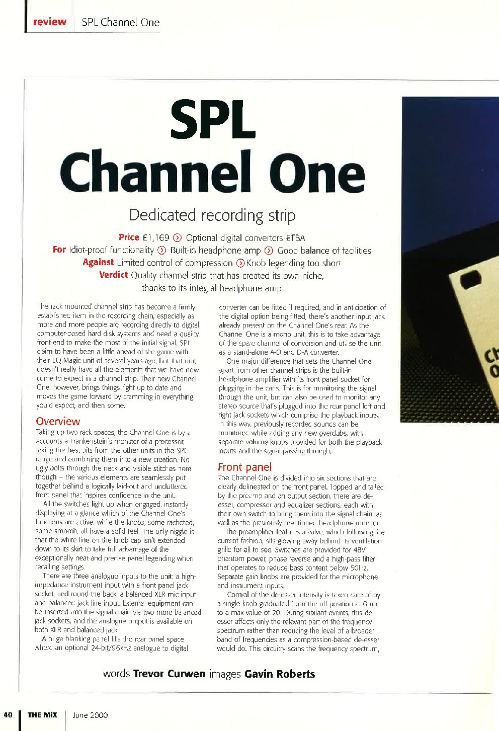
Channel One Mk3 is equipped with a discrete preamplifier.
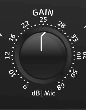
The gain control can be used to adjust the preamplification. For microphone signals, a preamplification of up to 68 dB can be realized – so even really demanding microphones can show their qualities. The control range for line signals ranges between -20 dB and +16 dB. The control range for instrument signals ranges between -6 dB and +30 dB.

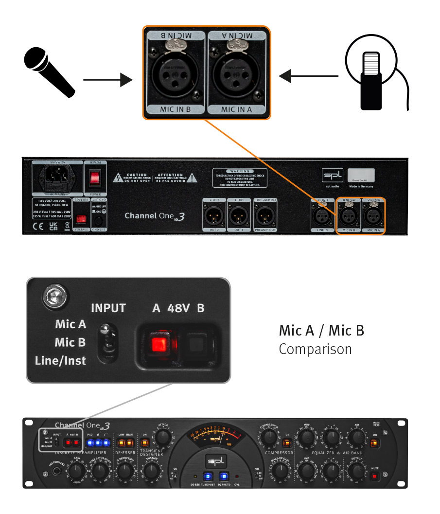
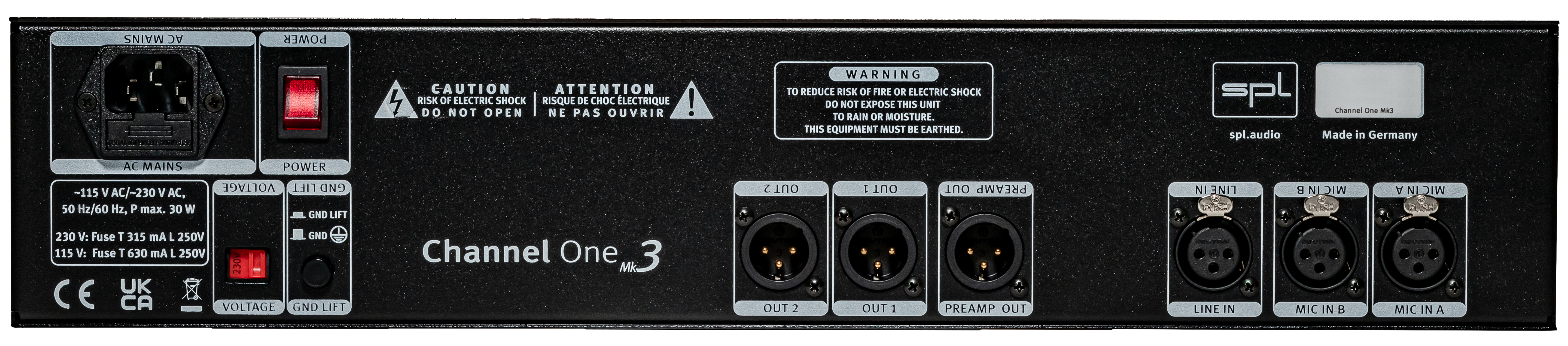
Channel One Mk3 offers two microphone inputs on the rear panel – Mic A and Mic B. Two microphones can be connected. This enormously simplifies the workflow. Thus, when comparing or changing microphones, it is no longer necessary to unplug them.

The 48V switch activates the phantom power of 48 volts required for the use of condenser microphones. Phantom power can be activated individually for both microphone inputs!
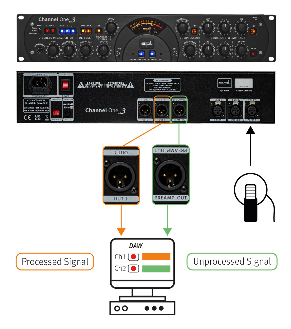
The Preamp Out picks up the signal directly after the microphone amplifier. This signal can also be recorded on a separate track in the DAW, for example, to be on the safe side. If it is noticed after a recording session that the singer was a little louder in the perfect take and therefore hits the compressor too hard, this incorrect setting can still be changed afterwards. The signal recorded for safety can later be played back into the Channel One Mk3 via the Line In and be processed there with Tube Saturation, Compressor or other tools.
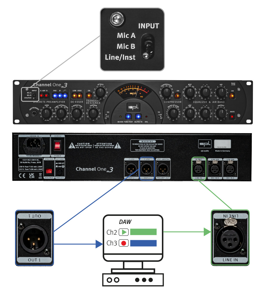
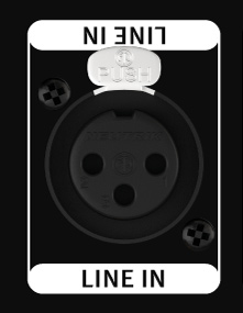
Channel One Mk3 offers the possibility to process line signals. This means that sources with line level, such as an analog signal from an audio interface, can be processed with de-esser, compressor, limiter and equalizer and then be recorded again. In this way, Channel One Mk3 becomes an “analog plugin” within an insert of a DAW.
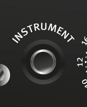
The low-noise instrument input is located easily accessible on the front.

The PAD switch attenuates the signal of the microphone input by 20 dB, so that even very high levels can be processed with the Channel One Mk3. This is the case, for example, with loud percussion or brass recordings.

The phase reverse function reverses the polarity of the signal. After pressing the switch, the phase is reversed by 180°.
Tip:
We recommend checking the correct polarity before recording and correcting it if necessary. The phase inversion function can be used, for example, to correct a headphone monitor signal that may be out of phase. A voiceover artist, for example, hears himself through the headphones and simultaneously through the bones in his head. Phase inversion will cause an unnatural sound, and even minimal variations in distance to the microphone will cause drastic variations in the sound. Phase inversion can be applied to the microphone, line and instrument inputs. In general, you can always just try out whether a phase reverse has a positive effect on certain signals in the mix.

A highpass filter with 6 dB per octave reduces impact noise below 80 Hz. This filter can be used for both preamplifiers.
With this control the amount of tube saturation can be determined. The output level is accommodated automatically, in extreme settings the level increases by only 6 dB. Therefore decent to expressive harmonic distortions can be easily dialed in by turning just one knob.
Saturation effects are generated through the tube being pushed to and beyond its normal operating limits. In contrast to semiconductors, a tube thus pushed to such levels does not clip from a certain level, approaching more gradually its level limits and thereby producing its typical tonal result, which in audio signal processing can have such often profitable aural effects — on one hand (and depending on the amount applied), from subtle to extensive harmonic distortion and on the other hand, a compaction of the sonic event, that is, a limiting effect that exhibits a pleasant, rounded or soft sound. Acoustically and also in its range of applications this can be compared very well with tape saturation effects.
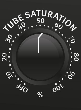

The Tube Post switch changes the order of the Tube Saturation within the signal flow: When the switch is pressed, the Tube Saturation stage comes after the EQ stage and before the output stage; when the switch is not pressed, the Tube Saturation stage comes directly after the preamp and before the de-esser.
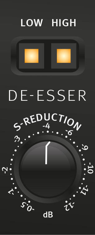
Unobtrusively and effectively, the Auto-Dynamic De-Esser removes distracting S‑sounds, in a mix or on vocal tracks, by detecting only the S‑frequencies, mixing them back into the main signal phase-inverted, and thus simply deleting sibilants in the original signal. The Auto-Threshold control maintains constant processing even as the singer’s distance from the microphone varies. The result is tonally neutral, unobtrusive and extremely effective. Even at high S‑reduction values, the de‑essing has no significant effect on the character and timbre of the voice.
SPL De-Esser use a unique technology to reduce sibiliance in a mix or on vocal tracks.
In contrast to common de-essers based upon compressor techniques the SPL De-Esser makes use of the phase cancellation principle. It employs filters that process only the reducible S-frequencies but do not interfere with the remainder of the spectrum. The S-frequencies are detected automatically, the phase is inverted and mixed with the original signal. This method of operation has distinct advantages because it is unobtrusive and helps retain the original tonal quality.
The reduction is accomplished by comparing the average level with the individual S-sounds: the de-esser functions only when the S-noise level exceeds the average level of the entire frequency spectrum. This means for example that original S-sounds with a certain S-portion are not processed whereas those that are too loud, or do not effectively contribute to the sound, are reduced – but the character of the voice remains unchanged.
A further specialty is the integrated Auto Threshold function which makes processing independent of the input level. Even when the speaker or singer does not maintain a constant distance to the microphone, processing is retained at the pre-set S-reduction value. Conventional systems are dependent on the input level and work more intensively as the distance to the microphone is reduced.
As a result, the SPL De-Esser does not need to be monitored and re-adjusted permanently to keep processing constant – and it can always be applied before the compressor, as changing its position would not be an advantage. That is why an accordant switching function is not necessary. The result is a sound-neutral, inconspicuous and extremely effective process.
Even at high S‑Reduction values the de-essing has an egligible effect on the character and timbre of the voice.

The S‑Reduction control adjusts the intensity of the S‑sound reduction.
In practice, S‑Reduction settings between -2 dB and -8 dB achieve the best results for most applications.
The Low and High switches can be used to activate or deactivate the low or high band de-esser, meaning a different center frequency for the de-esser. If no switch is pressed, the de-esser is not active. If the Low switch is pressed, the low de-esser band is activated with a center frequency of 6.4 kHz and a bandwidth of 4.4 kHz. If the High switch is pressed, the high de-essing band with a center frequency of 11.2 kHz and a bandwidth of 5.5 kHz is activated. If both switches are pressed, Low and High band de-esser are active.

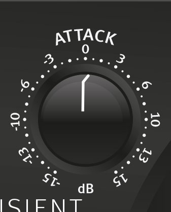
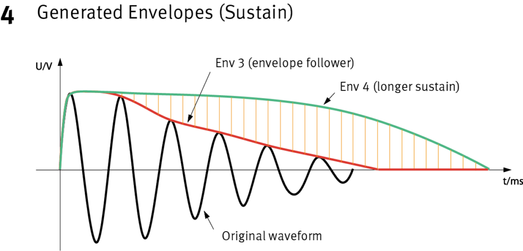
With the Transient Designer it is possible to manipulate the envelopes of audio signals level-independently (no threshold!). Accelerate or slow down transients, lengthen or shorten sustain times – with just two controls: attack and sustain.
All time constants are automated in a musical way and optimize themselves
adaptively according to the characteristics of the input signal.


The On switch activates the Transient Designer section, consisting of the Attack control and the Sustain control.
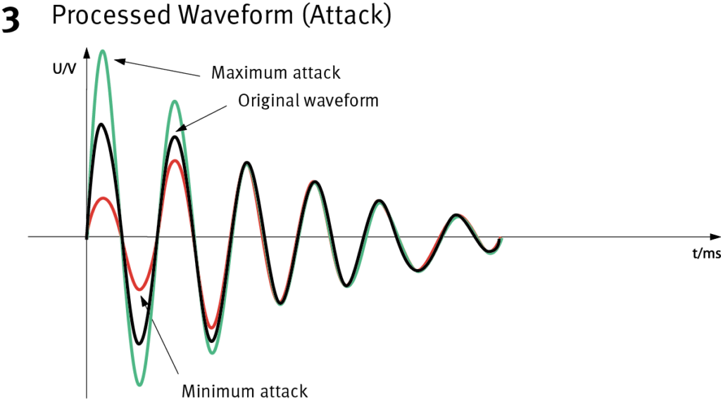
Attack can be used to increase or attenuate the transient phase of a signal by up to 15 dB. A positive attack value increases the amplitude of the transient response. Negative attack values lead to an attenuation.
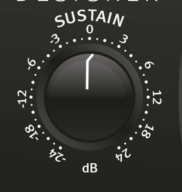
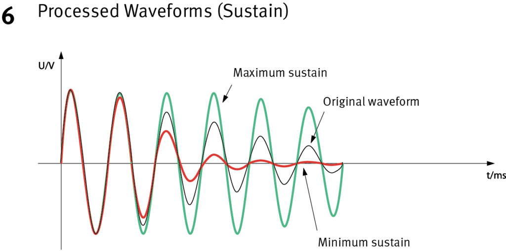
Sustain can be used to increase or attenuate the sustain phase of a signal by up to 24 dB. Positive sustain values extend the sustain. Negative Sustain values shorten the sustain.
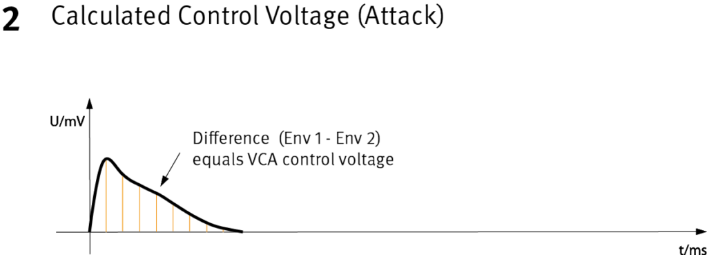
Differential Envelope Technology (DET) enables, through differential envelopes, level-independent processing of dynamic signal characteristics. Only two controls are needed to control the transient response. The envelope trackers align the working processes with the natural signal characteristics. This ensures optimum results for every moment.


“The Transient Designer has changed my working life.”

“I am a huge fan and use it on every project I do … nothing else does what it does.”

“I love my Transient Designer, I need more channels!”

“It is truly one of the most unique pieces of gear any mixer can have.”

The compressor is also extremely easy to operate with one knob only; its strength lies in its unobtrusive, musical operation.
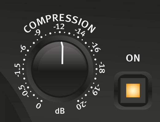
The Compression control can be used to set a threshold between 0 dB and -20 dB. The lower the threshold, the more the compressor works.

The Make-Up Gain control can be used to make up for the overall level reduction caused by compression. A value between 0 dB and 20 dB can be set by which the level is increased again after compression.
With the help of the Gain Reduction display on the panel, the adjustment is very simple: if the maximum reduction value caused by the loudest part is e.g. -9 dB, the Make-Up Gain control should be set to values around +9 dB.
The On switch activates the compressor section, consisting of the compression control and the Make-Up Gain.


The gain reduction can be displayed on the big VU meter. To do this, the VU switch on the right under the VU meter must be set to the GR position. This way, the VU meter displays the processing that is done with the compressor. On the VU meter, the level reduction caused by compression is displayed in dB.
In the Channel One Mk3 compressor, the parameters for the time constants (including attack and release) are set automatically and thus adapt to the changing conditions of the input signal better than it would ever be possible with a manual control.
The attack time of a compressor should respond quickly to explosive P or T sounds and act more slowly on soft onset sounds, otherwise sound coloration may occur. The compressor in the Channel One Mk3 therefore adjusts faster to large level increases than to small ones; long held notes are automatically processed with a long attack time.
The control of the release time also depends on the input signal. Fast and large increases in level are accordingly processed with shorter time constants than small increases in level. Comparable to the attack time control, small increases in level are adjusted with large time constants in order to keep the distortion of the audio signal as low as possible. This technique represents the perfect balance between fast, unobtrusive control behavior and the lowest possible distortion, resulting in a natural and transparent sound image.
Another circuit feature contributes to the high sound quality of the compressor in the Channel One Mk3: the dual VCA circuit. Two VCAs are used, one receives a phase-correct signal, the other a phase-inverted signal. The two signals then pass through a differential amplifier. The effect of this circuit is to eliminate distortion and offset transients, since the difference between the two signals eliminates the noise.
In addition, the individual VCAs share their job and are therefore not even close to being overdriven – the danger of
“offset” noises, audible as clicking or popping, is virtually eliminated. But the double VCA circuitry also exhibits significantly improved overall distortion and distortion values as a result, resulting in a much clearer and more transparent soundstage than with conventional circuitry. Voices and instruments sound much more natural and dynamic.


The center frequency of the half-parametric bass filter is set with the LMF control (low/mid frequencies).
The adjustable frequency range is between 30 Hz and 700 Hz so that this filter covers a range of about 4.5 octaves, allowing it to be used from the deepest bass to the lower mid range.
This together with the MHF filter ensures that the entire frequency spectrum is covered.
The -/+ control (right to the LMF control) determines the boost or cut of the LMF filter.
The maximum values are +/-12 dB. The LMF filter also operates to the proportional-Q-principle, in other words the bandwidth is dependent on the selected boost or cut. This filter characteristic permits a musically more sensible processing of the frequency spectrum than with constant-Q filters: if a more thorough setting has been chosen this will lead to far preciser definition of the frequency range to be processed. This in turn minimizes influences from adjacent ranges.
The boost or cut values, in relation to the bandwidth, lie somewhat higher than with the MHF filter. The bandwidth is therefore narrower at maximum boost than with the MHF filter for even more precise filtering. The LMF filter can be applied in many ways. Examples are; to accentuate the fundamental sound of a voice, to cut boom frequencies and for placement of bass emphasized instruments during recording or subsequently when mixing.
The center frequency of the semi-parametric mid/high frequency filter is set with the MHF control. (MHF: mid/high frequencies).
The frequency range can be set between 680 Hz and 15 kHz so that this filter covers a range of 4.5 octaves and can be equally employed in the lower mid as well as the high range.
The -/+ control determines the boost, or cut of the MHF filter; the maximum values are +/- 12 dB.
The MHF filter utilizes the proportional-Q-principle, too: the higher the boost or cut values are set, so the bandwidth becomes narrower; by low boost or cut values the bandwidth increases. The filter construction permits the complete scope, from selective removal of accentuated frequencies through to character giving accentuations of an instrument, to be effectively and quickly covered.

The high frequency filter in the equalizer module is described as Air. A coil-capacitor filter with so called bell characteristics and a center frequency of 19 kHz comes into operation here. At this frequency the maximum possible accentuation is +10 dB, the maximum possible damping is -10 dB.
The soft and natural tonal property, characteristic of the coil-capacitor filter, lends itself extremely well to provide clarity and air to vocals in the upper frequency range thereby improving their presence. On the other hand harsh sounds can be lent a more pleasant sound characteristic through damping.
The equalizer section is
activated via the On switch.

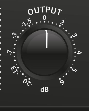
With the output control, the output level can be attenuated by up to -20 dB or amplified by a maximum of +6 dB. This ensures that following devices or AD converters can receive an optimal output level.
The respective set output level is displayed on the big VU meter when the VU switch is in the Out position.

The Mute switch mutes all output signals; when activated the VU meter displays no output level (VU meter switch in Out position).


The illuminated VU meter displays the input level, output level and gain reduction. With the VU switch on the right below the VU meter it is possible to select which level is displayed.
The VU switch on the right below the VU meter can be used to select which level is displayed in the VU meter.
GR: Gain Reduction
In: Input level
Out: Output level

For a better and more intuitive display of the signal levels the VU switch on the left side below the VU meter can be adjusted to the display range of the VU meter to different signal levels.
In switch position 0, 0 dB on the VU meter corresponds
to an output level of +6 dBu.
In the +6 switch position, 0 dB on the VU meter corresponds
to an output level of +12 dBu.
In the +12 switch position, 0 dB on the VU meter corresponds
to an output level of +18 dBu.
The OVL LED lights up as soon as an overload is detected in the device. The indicator picks up at all relevant points of the signal flow: after the preamp, after the tube saturation stage, after the Transient Designer, after the compressor, after the equalizer and after the output control. This ensures that the sonic processing achieves only positive effects and enhances every recording signal.


The DE-ESS LED lights up as soon as an S sound is detected. It is only active when the de-esser is switched on, but it works independently of the set reduction value. In other words, it always indicates that the circuit is detecting sibilants – so your attention is always drawn to any need for adjustment.
The EQ pre TD switch swaps the order of the Equalizer and Transient Designer: if the switch is pressed, the Equalizer is placed in front of the Transient Designer; if the switch is not pressed, the order remains unchanged.

The Tube Post switch changes the order of the tube saturation within the signal flow: When the switch is pressed, the Tube Saturation stage is after the Equalizer stage and before the Output stage; when the switch is not pressed, the Tube Saturation stage is directly after the Preamp and before the De-Esser.

The inputs and outputs of the Channel One Mk3 are equipped with Neutrik XLR sockets and plugs with gold-plated contacts. The signal transmission is electronically balanced, at a nominal level of +6 dBu.
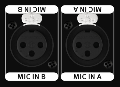
Microphones of all types can be connected to the Mic jack (dynamic, condenser, tube and ribbon). Channel One Mk3 offers two microphone inputs on the rear – for Mic A and Mic B. Two microphones can be connected here. This simplifies the work enormously. This means that you no longer have to plug in a different microphone when comparing or changing microphones.
The phantom power of 48 V required for some microphone types can be switched on individually for each of the two microphone inputs with the 48 V switch. A switching-delay relay circuit ensures that no noise is caused during switching.
Line signals usually have impedances lower than 1 kΩ. Such low impedance signals come e.g. from D/A converters, synthesizers or samplers.
The unbalanced instrument input is used to connect high-level, high-impedance (higher than 1 kΩ) instrument signals, such as an electric bass or guitar.
These balanced output jacks provide the output signal. The Channel One Mk3 provides two parallel outputs each.
Both have the same output signal. An additional external signal splitter for back-up systems during a recording session is therefore no longer necessary.

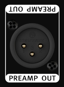
This balanced preamp-out is not to be underestimated.
This output is the pure pre-amplified microphone signal – without any processing of the Channel One Mk3’s processing tools.
Tip:
This signal can be recorded, on another track in parallel to the regular output signal of the Channel One Mk3 in the DAW. If the compressor was set a little too strong within the perfect take or the tube saturation should rather have been at the end of the processing chain – no problem!
The track with the signal from the Preamp Out can easily be sent back out of the DAW and into the Channel One Mk3’s processing chain via the Line input. This allows the settings to be changed as desired. This finished signal is then recorded back in the DAW – the perfect take has been saved!
Channel One Mk3 has a 4 mm thick, black anodized aluminum front panel and aluminum knobs milled from solid. The housing is made of high-quality steel and is powder-coated in elegant black.

With all SPL devices we develop not only according to plan, but also by ear. Many important components are installed on the circuit boards using Through-hole technology. This way we can ensure that we can use the best sounding components.

That’s why we manufacture all devices in our own production facility in Niederkrüchten on the Lower Rhine, Germany.

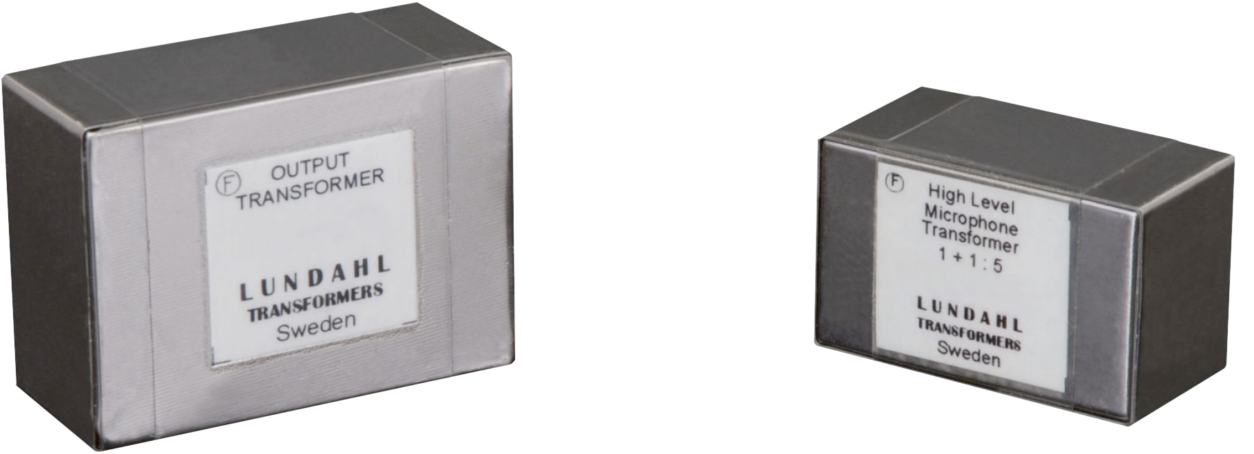
Transformers are used as an alternative to electronic balancing stages in the inputs and outputs. Transformers can be found in many classics of audio engineering. They make the bass and fundamental tines rounder and give it a little more punch. The high and overtone range sounds a bit silkier and more present.
We find transformers to be advantageous, especially for voices. For highest precision and speed in signal transmission (transient processing), however, electronic stages are better suited. The bottom line is that it is a question of taste and application.
In the case of preamplifiers or channel strips, the 2161 input transformer, which is specially designed for microphone inputs, provides an additional gain of up to 14 dB (depending on the microphone), which must then be added to the scaling. This relieves the microphone preamplifier. Since the transformer ratio passively increases the level, no noise is added. Therefore, the input transformer is more important than the output transformer in preamplifiers.
When equipped with input and output transformers and completely symmetrical cabling, no voltages can enter the device via the signal connections that could cause damage. The signal transmission is inductive and thus electrically isolated.
No hum is guaranteed. And last but not least, transformers drive very long cable runs, which is a welcome feature in live applications at the latest.
The Channel One Mk3 can be ordered with an optional input transformer for the
microphone inputs and an output transformer for the output Out 1.
The product with transformer is called:
Channel One Mk3 – Premium


0 dBu = 0,775V. Technische Änderungen vorbehalten.
In Stock!
The product is in stock in our warehouse in Niederkrüchten, Germany, and will be shipped the same or next working day.
We process the orders after receipt of the order and update the stock in the online shop regularly. If the product is no longer available at short notice due to high order volume, you naturally have the right to withdraw from the purchase (see Right of Withdrawal).
In any case, you will receive an e-mail with details of the delivery and the estimated delivery time.
Available soon!
The product is not in stock in our warehouse in Niederkrüchten, Germany. Usually it will be available again within 5 working days.
In any case, you will receive an e-mail with the details of the delivery and the estimated delivery time.
Of course you have the right to withdraw from your purchase (see Right of Withdrawal).
Currently unavailable.
This product is currently sold out and unavailable.
Auf Lager!
Das Produkt ist in unserem Lager Niederkrüchten vorrätig und wird noch am selben oder nächsten Werktag versendet.
Wir arbeiten die Bestellungen nach Bestelleingang ab und aktualisieren den Bestand im Online-Shop regelmäßig. Falls das Produkt wegen hohem Bestellaufkommens kurzfristig nicht mehr verfügbar ist, hast du selbstverständlich das Recht, vom Kauf zurückzutreten (siehe Widerrufbelehrung).
In jeden Fall erhältst du eine E-Mail mit den Einzelheiten der Lieferung und der voraussichtlichen Lieferzeit.
Bald verfügbar!
Das Produkt ist in unserem Lager Niederkrüchten nicht vorrätig. Gewöhnlich ist es innerhalb von 5 Werktagen wieder verfügbar.
Auf jeden Fall erhältst du eine E-Mail mit den Einzelheiten der Lieferung und der voraussichtlichen Lieferzeit.
Selbstverständlich hast du das Recht, vom Kauf zurückzutreten (siehe Widerrufbelehrung).
Zur Zeit nicht verfügbar.
Dieses Produkt ist derzeit ausverkauft und nicht verfügbar.

Due to Covid19 there are no events scheduled at this time.
Aufgrund von Covid19 sind derzeit keine Events geplant.
Notwendige Cookies sind für das ordnungsgemäße Funktionieren der Website unbedingt erforderlich. Diese Cookies stellen grundlegende Funktionalitäten und Sicherheitsmerkmale der Website sicher, anonymisiert.
| Cookie | Duration | Description |
|---|---|---|
| cookielawinfo-checbox-analytics | 11 months | This cookie is set by GDPR Cookie Consent plugin. The cookie is used to store the user consent for the cookies in the category "Analytics". |
| cookielawinfo-checbox-functional | 11 months | The cookie is set by GDPR cookie consent to record the user consent for the cookies in the category "Functional". |
| cookielawinfo-checbox-others | 11 months | This cookie is set by GDPR Cookie Consent plugin. The cookie is used to store the user consent for the cookies in the category "Other. |
| cookielawinfo-checkbox-advertisement | 1 year | The cookie is set by GDPR cookie consent to record the user consent for the cookies in the category "Advertisement". |
| cookielawinfo-checkbox-necessary | 11 months | This cookie is set by GDPR Cookie Consent plugin. The cookies is used to store the user consent for the cookies in the category "Necessary". |
| cookielawinfo-checkbox-performance | 11 months | This cookie is set by GDPR Cookie Consent plugin. The cookie is used to store the user consent for the cookies in the category "Performance". |
| gpnf_form_session_2 | 7 days | Saves entries of the spare parts request form |
| gpnf_form_session_4 | 7 days | Saves entries of the spare parts request form |
| viewed_cookie_policy | 11 months | The cookie is set by the GDPR Cookie Consent plugin and is used to store whether or not user has consented to the use of cookies. It does not store any personal data. |
Performance-Cookies werden verwendet, um die wichtigsten Leistungsindizes der Website zu verstehen und zu analysieren, was dazu beiträgt, den Besuchern ein besseres Benutzererlebnis zu bieten.
Andere nicht kategorisierte Cookies sind solche, die analysiert werden und noch nicht in eine Kategorie eingeordnet worden sind.
| Cookie | Duration | Description |
|---|---|---|
| complianz_policy_id | 1 year | No description |
Analytische Cookies werden verwendet, um zu verstehen, wie Besucher mit der Website interagieren. Diese Cookies helfen dabei, Informationen über Metriken wie die Anzahl der Besucher, Absprungrate, Verkehrsquelle usw. zu liefern.
Funktionale Cookies helfen dabei, bestimmte Funktionen auszuführen, wie z. B. das Teilen des Inhalts der Website auf Social-Media-Plattformen, das Sammeln von Feedbacks und andere Funktionen von Drittanbietern.
Werbe-Cookies werden verwendet, um Besuchern relevante Werbung und Marketing-Kampagnen anzubieten. Diese Cookies verfolgen Besucher über Websites hinweg und sammeln Informationen, um maßgeschneiderte Werbung bereitzustellen.